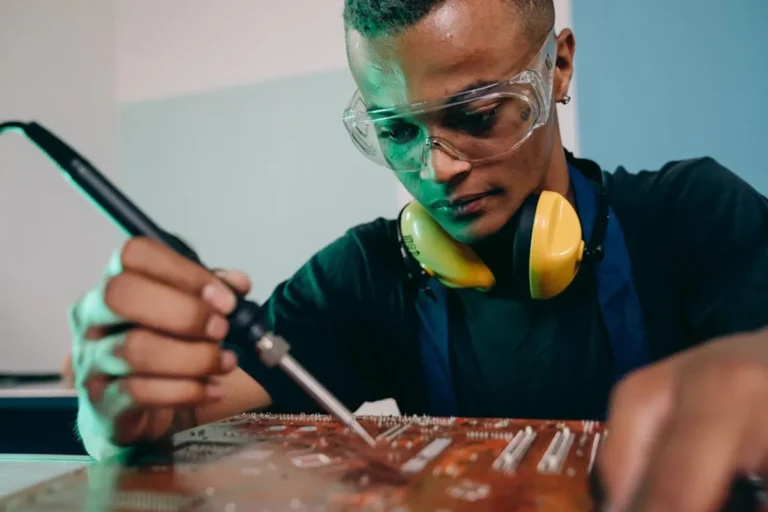

Developing new electronic products often involves navigating a complex landscape of design iterations, material sourcing, and manufacturing lead times. Traditional prototyping methods, relying on CNC machining or injection molding for enclosures and custom parts, frequently introduce significant delays and costs, especially in early development stages. This bottleneck can stifle innovation and extend time-to-market. Integrating 3D printing into the electronics prototyping workflow directly addresses these challenges by offering rapid, cost-effective, and highly customizable solutions for physical components, allowing engineers and product developers to test, refine, and validate designs with unprecedented speed and flexibility.
Why 3D Printing Transforms Electronics Prototyping
Accelerated Design Iteration
The core benefit of 3D printing in electronics prototyping is the speed of iteration. Design changes, from minor tweaks to major overhauls, can be implemented in CAD software and translated into a physical prototype within hours. This rapid turnaround allows for multiple design cycles in the time it would take to produce a single prototype using conventional methods. Engineers can quickly validate form, fit, and basic function, identifying and correcting issues early in the development process. This agility reduces the risk of costly redesigns later on and accelerates the overall product development timeline.
Cost Reduction in Early Stages
For low-volume, custom parts, 3D printing significantly cuts down on initial tooling and manufacturing costs. Traditional methods often require expensive molds or specialized machine setup, which are only economical at scale. With 3D printing, the cost per part remains relatively consistent regardless of volume, making it ideal for producing one-off prototypes or small batches for testing. This cost efficiency frees up budget for other critical development areas, such as circuit board design or software development.
Custom Enclosures and Form Factors
Electronics often require highly specific enclosures that fit unique form factors or integrate complex mounting points for components, connectors, and displays. 3D printing excels at producing these intricate geometries without additional cost or complexity. This enables designers to create ergonomic, compact, or aesthetically unique enclosures that would be challenging or prohibitively expensive to manufacture using traditional means during the prototyping phase. The ability to customize every detail allows for optimal component placement and thermal management from the outset.
Key 3D Printing Technologies for Electronics
Fused Deposition Modeling (FDM)
FDM is one of the most common and accessible 3D printing technologies. It works by extruding thermoplastic filament layer by layer.
Best for: Robust, functional prototypes, enclosures, and jigs where high detail isn't the absolute priority but strength and material variety are. Materials like ABS, PLA, and PETG offer different mechanical and thermal properties suitable for various applications.
Stereolithography (SLA)
SLA uses a UV laser to cure liquid photopolymer resin layer by layer. This process yields parts with very high resolution, smooth surfaces, and intricate details.
Best for: Enclosures requiring fine aesthetic detail, small component prototypes, transparent parts for light pipes or covers, and situations where visual fidelity is crucial for user experience testing.
Digital Light Processing (DLP)
Similar to SLA, DLP uses a digital projector screen to flash an image of each layer across the entire platform, curing the resin rapidly. This makes DLP generally faster than SLA for producing multiple parts simultaneously.
Best for: High-volume small part prototyping, precise component housings, and applications where speed of production and fine detail are both critical.
Multi-Material and Conductive Printing
Advanced 3D printing technologies now allow for the combination of multiple materials within a single print, including conductive inks or filaments. This capability opens doors for integrating circuit traces directly into a 3D structure.
Best for: Creating functional electronic prototypes with embedded circuitry, flexible electronics, and integrated sensors, reducing the need for separate PCBs in early-stage testing.
Pro Tip: When choosing a 3D printing technology for electronics prototyping, consider the specific requirements of your component. FDM is excellent for quick, low-cost functional enclosures, while SLA or DLP might be necessary for intricate details, smooth finishes, or transparent elements. Conductive printing offers unique advantages for integrating basic circuits directly into the prototype structure.
Practical Applications and Workflow Integration
Enclosure Design and Fit Testing
3D printing allows for rapid iteration of enclosure designs, ensuring perfect fit for PCBs, batteries, connectors, and user interface elements like buttons and screens. Designers can quickly print multiple versions to test ergonomics, aesthetic appeal, and assembly processes. This iterative approach minimizes costly tooling errors down the line.
Jig, Fixture, and Tooling Creation
Beyond end-use parts, 3D printing is invaluable for creating custom jigs and fixtures for assembly, testing, or soldering processes. These tools can significantly improve efficiency and consistency in a prototyping lab, tailored precisely to the unique geometry of the electronic components being handled.
Functional Component Integration
For prototypes requiring unique mechanical components—such as custom gears, levers, or mounting brackets—3D printing provides a fast path to functional testing. This includes creating custom heatsinks, fan mounts, or cable management solutions that perfectly integrate with the electronic assembly.
Optimizing Your 3D Printing Workflow
Material Selection Considerations
The choice of material directly impacts the functionality and durability of your prototype.
- PLA: Easy to print, good for aesthetic models and non-stress-bearing parts. Biodegradable.
- ABS: Stronger and more heat-resistant than PLA, suitable for functional parts and enclosures. Requires a heated bed.
- PETG: Combines the ease of printing PLA with the strength and durability of ABS, plus good chemical resistance.
- Flexible Filaments (e.g., TPU): Ideal for gaskets, strain reliefs, or parts requiring shock absorption.
- Resins (SLA/DLP): Offer high detail, smooth finishes, and can be engineered for specific properties like toughness, flexibility, or transparency.
- Conductive Filaments/Inks: For basic embedded circuits, shielding, or static dissipative applications.
Design for Additive Manufacturing (DfAM) Principles
To maximize the benefits of 3D printing, design your parts with the process in mind. This includes optimizing for minimal support structures, considering layer orientation for strength, designing interlocking features for multi-part assemblies, and integrating features that simplify post-processing. Understanding the limitations and strengths of your chosen printing technology will yield better results and reduce print failures.
Post-Processing and Finishing
Many 3D printed parts benefit from post-processing. This can range from simply removing support structures and light sanding to achieve a smooth finish, to vapor smoothing (for ABS), painting, or applying conductive coatings for EMI shielding. The level of finish required depends on the prototype’s purpose—a functional test piece might need minimal finishing, while a client-facing mockup will demand a higher aesthetic standard.
Scaling Up: From Prototype to Production
While 3D printing is a powerful prototyping tool, it's generally not economical for mass production of electronic enclosures or components due to slower speeds and higher material costs compared to injection molding or CNC. However, the prototypes created via 3D printing directly inform the design and tooling for these mass manufacturing methods. The ability to thoroughly test and validate designs with 3D printed parts minimizes the risk of expensive modifications once production tooling is committed, ensuring a smoother transition from development to market.
Actionable Steps for Integrating 3D Printing
To effectively integrate 3D printing into your electronics prototyping workflow, consider these steps:
- Identify Bottlenecks: Pinpoint areas in your current prototyping process where delays or costs are significant, often related to custom mechanical parts or enclosures.
- Invest in Equipment or Services: Determine if in-house 3D printers (FDM for affordability, SLA/DLP for detail) or external 3D printing services are more suitable for your needs.
- Develop CAD Expertise: Ensure your design team is proficient in CAD software capable of generating print-ready 3D models.
- Experiment with Materials: Test various filaments and resins to understand their properties and how they perform in your specific applications.
- Establish a Design-Print-Test Loop: Create a rapid iteration cycle where designs are quickly printed, tested, and feedback is immediately incorporated into the next design revision.
- Document Learnings: Keep a record of successful prints, material choices, and design optimizations to build an internal knowledge base.
Frequently Asked Questions
What types of electronic components can be 3D printed?
While silicon chips and complex circuit boards are not directly 3D printed for functional use, 3D printing excels at creating custom enclosures, mounting brackets, light pipes, ergonomic components, jigs, fixtures, and even basic conductive traces for early-stage functional prototypes.
Is 3D printing cost-effective for electronics prototyping?
Yes, especially for low-volume, custom parts and early-stage iterations. It eliminates the high upfront costs associated with traditional tooling (molds, dies) for injection molding or CNC machining, making design changes significantly cheaper and faster to implement.
How does 3D printing speed up product development?
3D printing accelerates development by enabling rapid design iteration. Engineers can print a physical prototype in hours, test it, identify flaws, and then quickly print an improved version, compressing development cycles and reducing time-to-market compared to traditional methods.
What are the limitations of using 3D printing for electronics?
Current limitations include the inability to print highly complex, multi-layer PCBs or micro-scale electronic components with high reliability. Material properties like conductivity, heat resistance, and dielectric strength may not always match those of production-grade materials, necessitating careful selection and testing.