
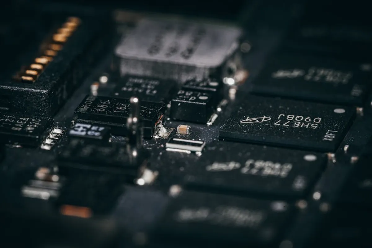
Embarking on electronics projects offers immense satisfaction, yet the initial learning curve often presents unexpected challenges. Beginners frequently encounter common pitfalls that can lead to component damage, circuit malfunction, or project abandonment. Understanding these prevalent mistakes from the outset can save significant time, material costs, and frustration. This guide identifies critical errors made by those new to electronics, offering practical insights to prevent them and foster more successful, efficient project development.
Fundamental Errors in Component Handling and Selection
Incorrect Component Polarity
Many electronic components are sensitive to the direction of current flow or voltage application. Diodes, including LEDs, only allow current in one direction; reversing them prevents operation and can cause damage if excessive voltage is applied. Electrolytic capacitors have distinct positive and negative terminals; connecting them in reverse can lead to overheating, bulging, or even explosion due to internal chemical reactions. Integrated circuits (ICs) also have specific pin orientations, often indicated by a dot or notch; incorrect insertion can permanently damage the chip or the circuit board. Always verify component datasheets and markings before installation.
Overlooking Component Ratings
Every electronic component operates within specified limits for voltage, current, and power. Exceeding these ratings is a primary cause of premature failure. For instance, connecting a 5V-rated component to a 12V supply without proper voltage regulation will likely destroy it. Similarly, drawing more current through a resistor or transistor than it's designed to handle will cause it to overheat and fail. Power ratings (measured in watts) dictate how much heat a component can safely dissipate. Ignoring these specifications results in unreliable circuits, component burnout, and potential safety hazards. Always calculate required ratings and select components with sufficient headroom.
ESD Damage
Electrostatic discharge (ESD) is a silent killer of sensitive electronic components, particularly integrated circuits. A static charge, often imperceptible to humans, can generate thousands of volts, creating micro-damage within semiconductor junctions. This damage might not cause immediate failure but can lead to intermittent issues or reduced lifespan. Prevention is crucial:
- Work on an anti-static mat connected to earth ground.
- Wear an ESD wrist strap connected to the mat or a grounded point.
- Handle sensitive components by their edges, minimizing contact with pins.
- Store components in anti-static bags until ready for use.
These measures protect components from invisible, irreversible damage.
Soldering and Connection Pitfalls
Cold Solder Joints
A cold solder joint occurs when the solder does not properly bond with both the component lead and the PCB pad. This typically happens due to insufficient heat, movement during cooling, or dirty surfaces. Visually, a cold joint appears dull, lumpy, or granular, unlike a shiny, smooth, concave fillet. Electrically, cold joints create intermittent or high-resistance connections, leading to unreliable circuit operation or complete failure. Proper technique involves heating both the lead and the pad simultaneously, applying solder to the heated joint, and allowing it to cool undisturbed.
Solder Bridges and Shorts
Solder bridges are unintended connections between two or more adjacent pads or traces on a circuit board, typically caused by applying too much solder or poor control during soldering. These bridges create short circuits, bypassing intended signal paths or connecting power to ground, which can damage components or the power supply. Always inspect soldered connections thoroughly, preferably with magnification, to identify and remove any bridges before applying power. Using the correct amount of solder and a fine-tipped iron helps prevent this issue.
Improper Wire Stripping and Connection
Incorrect wire preparation can introduce numerous problems. Stripping too much insulation exposes excessive bare wire, increasing the risk of accidental shorts. Stripping too little makes it difficult to achieve a secure connection. Nicking the wire strands during stripping reduces the wire's current-carrying capacity and mechanical strength, making it prone to breakage. Loose screw terminal connections, poorly crimped connectors, or inadequate strain relief can also lead to intermittent contact or complete disconnections under vibration or stress. Use appropriate tools and techniques for clean, secure wire terminations.
Design and Power Supply Missteps
Inadequate Power Supply Sizing
Many beginners underestimate the current requirements of their circuits. An undersized power supply cannot deliver the necessary current, leading to voltage drops, unstable operation, or the supply itself overheating and failing. Always sum the peak current draw of all components in your circuit and select a power supply with a current rating at least 20-30% higher than this total. Consider voltage regulation and ripple; unregulated supplies can have significant voltage fluctuations under load, impacting sensitive ICs. Always sum the peak current draw of all components in your circuit and select a power supply with a current rating at least 20-30% higher than this total, as detailed in our advice on choosing power supplies for electronics projects.
Neglecting Decoupling Capacitors
Decoupling capacitors, often small ceramic capacitors placed close to the power pins of integrated circuits, are crucial for stable operation. They act as local reservoirs of charge, smoothing out transient current demands and filtering high-frequency noise from the power supply lines. Without them, ICs can experience voltage dips during switching, leading to erratic behavior, errors, or even system crashes. Always include appropriate decoupling capacitors (e.g., 0.1µF) for each IC in your design, placed as close to the power pins as possible.
Ignoring Current Limiting Resistors
LEDs and certain other components require current limiting to prevent damage. Connecting an LED directly to a voltage source without a series resistor will cause excessive current to flow, burning out the LED almost instantly. The resistor's value is calculated based on the supply voltage, the LED's forward voltage, and its desired operating current. Failing to implement proper current limiting is a common and easily avoidable mistake that frequently leads to component destruction.
Pro Tip: Before applying power to any new circuit, perform a thorough visual inspection and a continuity check. Use a multimeter to verify there are no unintended shorts between power and ground, and that all critical connections are present. This preventative step can save components from immediate damage and simplify troubleshooting significantly.
Debugging and Testing Blunders
Rushing to Power On
The impulse to immediately power on a newly assembled circuit is strong, but it's often a critical mistake. A systematic pre-power-up checklist can prevent costly damage. This includes checking for solder bridges, correct component placement and orientation, proper wire connections, and verifying power supply voltage and polarity. A quick check with a multimeter for shorts between power and ground rails can avert immediate component failure.
Inefficient Troubleshooting
When a circuit doesn't work, random probing or replacing components without a clear strategy is inefficient and often counterproductive. Effective troubleshooting involves a methodical approach:
- Verify power supply: Is the correct voltage present at all points?
- Check continuity: Are all intended connections made? Are there any breaks?
- Isolate sections: Divide the circuit into logical blocks and test each independently.
- Use a schematic: Compare actual measurements to expected values at key points.
- Look for common failures: Start with power, ground, and clock signals.
A systematic approach pinpoints the problem faster and reduces further damage.
Improper Use of Multimeters
The multimeter is an essential tool, but improper use can lead to inaccurate readings or damage to the meter or circuit. A common mistake is attempting to measure current (amps) by connecting the multimeter in parallel across a voltage source, which effectively shorts the circuit and can blow the meter's fuse or damage the power supply. Current must always be measured in series with the load. Similarly, measuring voltage with the meter set to resistance or continuity mode will yield incorrect results. Always select the correct function and range before taking a measurement.
Cultivating Precision in Electronics
Mastering electronics involves more than just understanding theory; it requires meticulous attention to detail and a methodical approach to construction and testing. By actively avoiding these common beginner mistakes—from respecting component polarity and ratings to employing proper soldering techniques and systematic debugging—you build a foundation for reliable and functional projects. Invest time in careful planning, thorough inspection, and continuous learning from both successes and failures. This disciplined practice not only prevents costly errors but also accelerates your development into a proficient electronics enthusiast or professional.
FAQ
What is the most common mistake beginners make with LEDs?
The most common mistake is connecting an LED directly to a power source without a current-limiting resistor. This causes excessive current to flow through the LED, burning it out almost instantly.
How can I prevent electrostatic discharge (ESD) damage?
To prevent ESD damage, work on an anti-static mat, wear an ESD wrist strap connected to ground, and handle sensitive components by their non-conductive edges. Store components in anti-static bags when not in use.
Why do my circuits sometimes work intermittently?
Intermittent circuit operation is often caused by cold solder joints, loose connections, or inadequate decoupling capacitors. These issues can lead to unreliable electrical contact or power supply instability, manifesting as sporadic functionality.
What should I do if my circuit doesn't power on?
First, verify the power supply is delivering the correct voltage and current. Then, use a multimeter to check for any shorts between power and ground rails. Systematically check connections, component orientations, and continuity across critical paths, comparing your circuit to the schematic.