Embarking on DIY electronics can seem daunting, but selecting the right introductory project is key to building confidence and foundational skills. The initial choice dictates not only the complexity of the components and tools required but also the specific concepts learned, from basic circuit theory to soldering techniques and microcontroller programming. For beginners, the objective is to find projects that offer clear, achievable outcomes with minimal frustration, while still providing tangible educational value. This guide outlines accessible electronics projects, detailing their practical applications, the fundamental skills they impart, and the typical challenges encountered, enabling a more informed selection for those stepping into the field. Understanding the basic circuit components is the first step toward mastering these projects and building confidence.
What to Consider Before Starting Your First Electronics Project
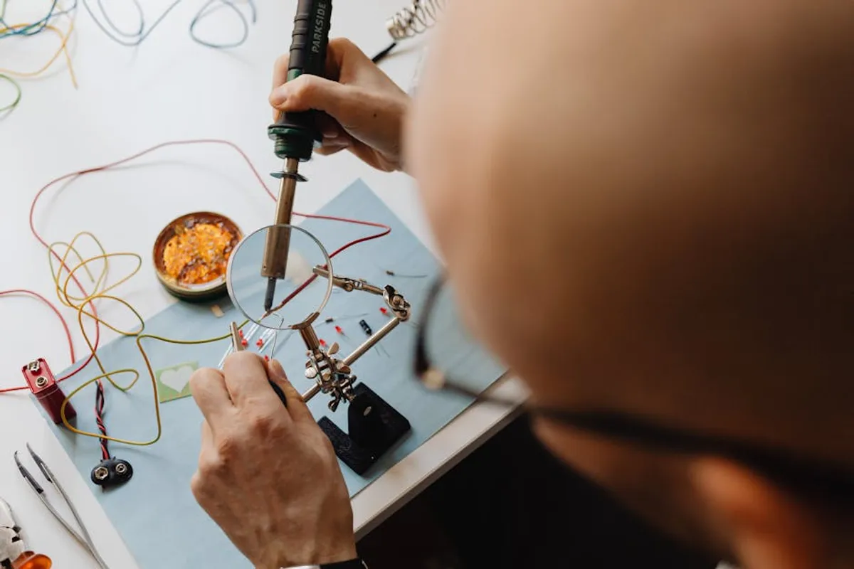
Before committing to a specific project, evaluate several factors to ensure a productive and enjoyable learning experience. First, assess the required tools; many beginner projects demand only a soldering iron, multimeter, breadboard, and basic hand tools. Second, consider the budget for components; some projects rely on inexpensive discrete parts, while others might involve microcontrollers or specialized sensors that increase cost. Third, understand the core learning objective: do you want to master soldering, understand voltage dividers, or delve into basic programming? Aligning the project with a specific learning goal enhances its educational impact. Finally, prioritize safety: always work in a well-ventilated area, use eye protection, and understand the power requirements of your circuit to avoid damage or injury.
1. Simple LED Blinker Circuit
The LED blinker circuit is often the first hands-on project for electronics enthusiasts, serving as a fundamental introduction to basic components and circuit assembly. Typically employing a 555 timer IC, resistors, capacitors, and an LED, this project demonstrates the principles of oscillation and timing. Its simplicity makes it an ideal exercise for learning to read schematics, identify component polarities, and practice basic soldering or breadboarding techniques. The immediate visual feedback of a blinking LED provides instant gratification and reinforces understanding of the circuit's function.
Best for: Absolute beginners seeking to understand basic circuit construction, component identification, and the role of timing circuits without complex programming.
Pros:
- Requires minimal, inexpensive components.
- Provides immediate, clear visual feedback of success.
- Excellent for practicing soldering or breadboard assembly.
- Introduces the versatile 555 timer IC, a cornerstone component.
Cons:
- Limited practical application beyond demonstrating principles.
- Can be overly simplistic for those with some prior experience.
Verdict: An indispensable starting point that builds fundamental assembly skills and introduces basic timing concepts, crucial for subsequent, more complex endeavors.
2. Light-Activated Switch
This project introduces beginners to sensor-based control by using a photoresistor (LDR) to detect ambient light levels and activate a switch, typically a relay or a transistor controlling an LED. It demonstrates how a change in environmental conditions can trigger an electronic response. Learners will encounter concepts like voltage dividers, transistor switching, and the basic operation of a relay. It’s a practical application of analog input influencing digital output, laying groundwork for automation and control systems.
Best for: Beginners interested in sensor integration, basic automation, and understanding how light can control electronic devices.
Pros:
- Teaches about light-dependent resistors and their application.
- Introduces transistor switching or relay control.
- Offers a tangible automation outcome (e.g., turning on a light in darkness).
- Components are readily available and affordable.
Cons:
- May require careful calibration of the photoresistor's sensitivity.
- Relay circuits can involve higher currents, demanding attention to safety.
Verdict: A highly practical project that bridges basic component understanding with real-world sensor applications, ideal for those looking to build simple automated systems.
3. Continuity Tester
A continuity tester is a simple, yet invaluable, diagnostic tool for any electronics workbench. This project involves building a circuit that emits a sound or illuminates an LED when a continuous electrical path is detected between two probes. It teaches about basic resistance, open and closed circuits, and the use of buzzers or LEDs as indicators. Constructing this tool provides practical experience and yields a useful device for troubleshooting wiring, checking fuse integrity, or verifying solder joints.
Best for: Learners who want to build a practical tool while understanding basic circuit testing and diagnostics.
Pros:
- Results in a highly functional and useful workshop tool.
- Reinforces understanding of open/closed circuits and resistance.
- Components are minimal and very inexpensive.
- Excellent for practicing compact circuit design and enclosure fitting.
Cons:
- Circuit complexity is very low, offering limited advanced learning.
- Output is binary (continuous/not continuous), lacking quantitative measurement.
Verdict: An excellent entry-level project that provides immediate utility and solidifies understanding of fundamental electrical principles through practical application.
4. USB Charger Detector
This project involves creating a simple device that indicates whether a USB port is supplying power or if a USB cable is faulty. It typically uses an LED and a resistor connected across the data or power lines of a USB connector. This project helps beginners understand the basic pinout of a USB connector, the concept of voltage presence, and how to safely tap into a power source. It's a quick build that results in a practical diagnostic tool for common electronics issues.
Best for: Beginners interested in practical diagnostic tools, understanding common interfaces like USB, and safe power handling.
Pros:
- Highly practical for everyday troubleshooting of USB devices.
- Teaches about USB pin configurations and voltage presence.
- Very few components required, making it quick and cheap to build.
- Offers a clear, immediate indication of functionality.
Cons:
- Does not involve complex circuit design or advanced components.
- Limited to detecting power, not data integrity or speed.
Verdict: A straightforward and immediately useful project that demystifies a common interface and provides a valuable diagnostic aid for any electronics enthusiast.
5. Simple Audio Amplifier
Building a basic audio amplifier, often using a single integrated circuit like the LM386, introduces beginners to analog signal processing and sound amplification. This project involves inputting a low-level audio signal (e.g., from a phone) and outputting an amplified signal to a small speaker. Learners will explore concepts such as gain, impedance matching, and decoupling capacitors. It provides a satisfying outcome with audible feedback and offers a clear pathway to understanding more complex audio circuits.
Best for: Those interested in audio electronics, signal processing, and understanding how to amplify weak signals for practical use.
Pros:
- Produces an audible, tangible result.
- Introduces basic audio ICs and their application.
- Teaches about input/output impedance and power delivery to a speaker.
- Can be expanded with volume controls or tone adjustments.
Cons:
- Requires careful attention to grounding and noise reduction for clean audio.
- Component count is slightly higher than simpler projects.
Verdict: A rewarding project that provides a solid introduction to analog electronics, culminating in a functional device with clear, auditory feedback.
6. Rain Sensor Alarm
A rain sensor alarm project utilizes a simple circuit board with exposed traces that, when bridged by water, complete a circuit and trigger an alarm (buzzer or LED). This project introduces the concept of conductivity, basic sensor design, and simple threshold detection. It’s an excellent way to understand how environmental conditions can be converted into electrical signals and used for practical alerts. The project often involves a transistor as a switch or a 555 timer to drive the alarm.
Best for: Beginners interested in environmental sensing, basic alarm systems, and the principles of conductivity.
Pros:
- Directly applicable for practical home automation or garden monitoring.
- Teaches about sensor construction and environmental interaction.
- Components are inexpensive and widely available.
- Offers clear, immediate feedback upon water detection.
Cons:
- Sensor longevity can be affected by corrosion if not properly designed.
- Sensitivity might need adjustment depending on application.
Verdict: A practical and engaging project that demonstrates how simple conductive properties can be harnessed for effective environmental monitoring and alerting.
7. Adjustable Power Supply
Building a simple adjustable power supply, often based on a voltage regulator IC like the LM317, allows beginners to create a versatile tool for their workbench. This project involves transforming an input voltage (e.g., from a wall adapter) into a stable, adjustable output voltage. Learners will gain experience with voltage regulation, rectification (if using AC input), filtering, and the use of potentiometers for variable control. It provides a deep dive into power electronics fundamentals.
Best for: Those who need a flexible power source for future projects and want to understand the principles of voltage regulation and power conversion.
Pros:
- Yields a highly useful and reusable piece of test equipment.
- Teaches crucial concepts in power electronics: regulation, filtering, rectification.
- Can be customized for various voltage and current requirements.
- Enhances safety by providing controlled power to circuits.
Cons:
- Requires careful component selection for heat dissipation and current handling.
- Can involve higher voltages, demanding strict adherence to safety protocols.
Verdict: A foundational project that equips the builder with an essential tool and a comprehensive understanding of stable power delivery, critical for all subsequent electronics work.
8. Digital Dice with 555 Timer and Counter IC
This project simulates a traditional six-sided die using electronics. It typically involves a 555 timer to generate clock pulses, a decade counter IC (like the 4017) to cycle through states, and LEDs arranged to display numbers 1 through 6. This project is an excellent introduction to digital logic, clock signals, and sequential circuits. It combines analog timing with digital counting and display, offering a clear illustration of how these concepts interact.
Best for: Beginners interested in digital logic, counting circuits, and combining analog timing with digital display.
Pros:
- Introduces fundamental digital ICs (counter, logic gates).
- Combines analog (555 timer) and digital components.
- Provides a clear, interactive demonstration of counting and display.
- Components are relatively inexpensive and widely available.
Cons:
- Requires understanding of multiple ICs and their interconnections.
- Can be slightly more complex than purely analog projects.
Verdict: A highly engaging project that offers a practical gateway into digital electronics, demonstrating how sequential logic can create interactive and fun applications.
9. Simple Temperature Sensor Display (with Arduino)
Integrating a temperature sensor (like the LM35 or DHT11) with a microcontroller like an Arduino and displaying the readings on an LCD or serial monitor introduces beginners to microcontrollers, programming, and sensor interfacing. This project moves beyond purely analog or discrete component circuits into the realm of embedded systems. Learners gain experience with basic C++ programming, digital communication protocols, and interpreting sensor data. It's a stepping stone to more complex data acquisition and control systems.
Best for: Those ready to delve into microcontroller programming, sensor data acquisition, and building interactive digital displays.
Pros:
- Introduces microcontroller programming (Arduino IDE).
- Teaches sensor interfacing and data interpretation.
- Provides a foundation for more complex embedded systems.
- Results in a practical device for environmental monitoring.
Cons:
- Requires learning a new programming language and development environment.
- Initial setup costs for Arduino and display can be higher than discrete components.
Verdict: An essential project for transitioning into the world of microcontrollers, offering significant learning in programming, sensor integration, and digital output.
10. Basic Robot Chassis with Motor Control
Constructing a simple robot chassis with basic motor control involves assembling mechanical parts and integrating a circuit to drive DC motors. This project introduces beginners to electromechanical systems, motor drivers (like the L293D H-bridge), and power considerations for moving parts. It can be controlled manually with switches or later expanded with sensors and microcontrollers for autonomous movement. It's a tangible way to see electronics interact with the physical world. This chassis can be a great starting point for more advanced Arduino project ideas involving robotics and automation.
Best for: Learners interested in robotics, electromechanics, and understanding how to control physical motion with electronics.
Pros:
- Combines mechanical assembly with electronic motor control.
- Introduces motor driver ICs and power management for motors.
- Provides a tangible, moving outcome, which is highly motivating.
- Offers a platform for future expansion with sensors and AI.
Cons:
- Requires some mechanical assembly skills in addition to electronics.
- Power requirements for motors can be higher, needing robust power supplies.
Verdict: A highly engaging project for those drawn to robotics, offering a practical blend of mechanical construction and electronic control over physical movement.
11. Capacitance Meter (Simple)
A simple capacitance meter project, often built using a 555 timer IC, allows beginners to measure the capacitance of various components. This circuit typically works by charging and discharging a capacitor through a known resistor and measuring the resulting time constant or frequency. It provides an excellent opportunity to understand the behavior of capacitors, RC time constants, and how timing circuits can be used for measurement. The output can be indicated by an LED's blink rate or a multimeter reading.
Best for: Those seeking to understand capacitor behavior, RC circuits, and building a diagnostic tool for component testing.
Pros:
- Provides a practical tool for testing and identifying capacitors.
- Deepens understanding of capacitance, resistance, and time constants.
- Utilizes the versatile 555 timer IC in a measurement context.
- Components are relatively simple and accessible.
Cons:
- Accuracy may be limited compared to commercial meters.
- Requires a separate multimeter to interpret the output frequency or voltage for actual capacitance values.
Verdict: An insightful project that demystifies capacitor function and RC circuits, yielding a useful, albeit basic, diagnostic tool for the workbench.
12. Morse Code Practice Oscillator
This project involves building a simple audio oscillator circuit (often using a 555 timer or a couple of transistors) that produces a tone when a momentary switch (key) is pressed. It’s an excellent way to learn about audio generation, basic oscillation, and switch debouncing. The project serves a practical purpose for practicing Morse code, making it both educational and functional. It reinforces basic circuit construction and the relationship between components and sound output.
Best for: Beginners interested in audio generation, simple oscillation circuits, and a practical application for learning a skill like Morse code.
Pros:
- Introduces basic audio oscillator principles.
- Provides a functional tool for learning and practicing Morse code.
- Components are minimal and inexpensive.
- Offers clear audible feedback.
Cons:
- Circuit is relatively simple, offering limited advanced electronics concepts.
- Primary utility is specialized (Morse code practice).
Verdict: A straightforward and engaging project that teaches fundamental audio circuit design while providing a unique and practical application for a niche skill.
Choosing Your First Project
The selection of your first DIY electronics project should align with your specific learning objectives and available resources. If your primary goal is to master soldering, a project with numerous through-hole components like the LED Blinker or Continuity Tester is ideal. For those keen on understanding how sensors interact with circuits, the Light-Activated Switch or Rain Sensor Alarm provides direct experience. If microcontroller programming is the desired path, the Temperature Sensor Display offers a practical entry point. Consider the complexity of the schematic, the number of unique components, and the required tools. Starting with a project that offers a clear, achievable outcome, even if simple, builds confidence and provides a solid foundation for more ambitious undertakings. Prioritize safety and methodical assembly to ensure a positive initial experience.
Frequently Asked Questions
What basic tools do I need to start DIY electronics projects?
Essential tools include a soldering iron with fine tips, solder, a desoldering pump or braid, a multimeter for testing voltage and continuity, a breadboard for prototyping, jumper wires, wire strippers, and small pliers or cutters. Safety glasses are also crucial.
Are electronics projects dangerous for beginners?
Most beginner projects operate at low voltages (e.g., 5V or 9V) and currents, posing minimal risk. However, projects involving AC power or higher voltages (like some power supplies) require extra caution. Always follow safety guidelines, ensure proper ventilation, and disconnect power before making changes to a live circuit.
Where can I find components for these projects?
Components are widely available from online electronics retailers, local hobby shops, and specialized distributors. Many projects use common, inexpensive parts that are easy to source individually or as part of beginner kits.
How do I troubleshoot if my project isn't working?
Troubleshooting involves systematically checking connections, component orientation (e.g., LED polarity, IC pin 1), solder joints for bridges or cold connections, and power supply. A multimeter is invaluable for checking continuity, voltage levels, and resistance. Consulting online forums or project guides can also provide common troubleshooting steps.
What is the difference between a breadboard and a PCB?
A breadboard is a reusable prototyping platform that allows components to be inserted and connected without soldering, ideal for testing circuits. A Printed Circuit Board (PCB) is a permanent board with conductive traces where components are soldered, creating a robust and compact final circuit.